GSHP Thermal Collector Pipework
This article details the pipe spacings and depths for closed-loop thermal collector pipes (or ground-coupled heat exchanger or ground loop) serving Ground Source Heat Pumps (GSHP).
Heat extraction can be obtained by using either shallow horizontal ground heat exchangers (horizontal loops) positioned between 0.8 and 2.0 m underneath the ground level or vertical borehole heat exchangers (vertical loops) typical 60 - 120 m deep. The area required for the collector pipework can be estimated from BS EN 15450.
A message from a sponsor
Ground Heat Exchanger Area
The annual heat extracted per square meter of ground heat exchanger (the collector area) must be determined since this value effects the continuous long term heat extraction. The heat extraction rate depends upon the quality of the ground and the duration of heat extraction (operation period of the heat pump in hours per year). The value should be between 50 and 70 kWh/m2 per year for heating operation only.
The minimum active ground heat exchanger pipe length can be calculated using methods detailed in MIS 3005-D The Heat Pump Standard (Design) published by MCS. The estimated total heat energy demand over a year for space heating domestic hot water is required to establish a Full Load Equivalent (FLEQ) run hours to use MCS tables for maximum power extracted per unit length of either a borehole, horizontal ground, or slinky ground heat exchanger.
Obstructions and over shading
The thermal capacity of ground located near buildings or vegetation can be compromised due to limited surface exposure to solar irradiation. Boreholes placed within 7 metres of such obstructions may experience reduced direct solar gain from cast shadows. In addition, restricted sky view lowers diffuse solar radiation levels, further diminishing the ground's ability to recover thermal energy effectively. Maintaining a separation of 10 metres from buildings and vegetation is advisable to ensure optimal thermal recovery and system efficiency over time. This distance also offers a safe buffer from structural foundations and underground utilities, facilitating future maintenance and reducing potential risks.
General Non-Active Distribution
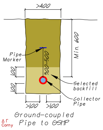
The non-active buried flow and return pipes (header pipes) from the heat pump to the active ground heat exchanger area should be installed in accordance with the information below. The dimensions provided are representative of industry guidance which does vary between sources.
It is important to observe the following:
- The minimum depth of pipe at any point should not be less than 600 mm.
- Pipes must be protected against frost. As the pipe fluid is pumped, and extracting heat from the ground, the frost-free depth differs from potable water services.
- The local average ground temperature should be established.
- Ground temperature at 2 m depth varies by approximately +/− 3 °C during the year.
- The ground temperature seasonal variation decreases with increasing depth.
- Below 15 m there is negligible seasonal temperature variation.
- Extracting heat will cool the ground over time.

Diagram from BS EN15450: Theoretical temperature distribution versus depth for a location with 10 °C annual mean external temperature
Depth, Width & Spacing:
- The minimum depth of pipe at any point should not be less than 600 mm.
- The trench depth may need to be increased by 100 mm for back filling if the bed surface is uneven.
- Pipes between an external manifold arrangement and the plant room should be separated by at least 700 mm or be insulated.
- Minimum trench width should be around 400 mm to allow space for back-filling that provides an even and continuous support and contact with the pipe.
- Minimum separation for horizontal ground loop should be 750 mm.
- Generally, wider spaced pipe loops and deeper installed pipe depths provide better heat extraction performance over the long term.

Clearance:
- No part of the ground collector area should be built over.
- Trenches should be a minimum of 1,000 mm clear of all building foundations (obviously the circuit will need to extend to the property).
- Ground pipe loops should be at least 2 metres from a building, although greater than 5 metres is better. Refer to obstructions notes here.
- Trenches should be a minimum of 1,500 mm clear of the site boundary. Between 3-5 metres is preferable.
- Pipes should have a minimum 1,500 mm clearance from a water main (see below).
- Pipes should have a minimum 1,000 mm clearance from a drain (see below).
- Alternatively, all pipes crossing water mains or drains should be separated by at least 500 mm and insulated a minimum 500 mm either side of crossing point.
Read Homemicro.co.uk's guidance on Thermal Insulation
General Installation:
- Pipes must be laid and surrounded (bed, side fill and top cover) by a material free of hard and soft spots which will provide even and continuous support and contact.
- Where ground conditions do not provide a suitably even bed, a minimum of 100 mm below the pipe should be supported on a compacted fine fill material such as sand.
- The side fill and a minimum of 100 mm minimum cover above the pipe must be sorted back fill or a compacted fine fill material such as sand.
- Detectable underground warning tape with an inbuilt stainless steel wire or aluminium foil should be laid approximately 300 - 500 mm above the buried pipes.
Horizontal Ground Loops
Shallow horizontal ground loops are suitable for most ground conditions where sufficient area is available excepted for dry sandy soils that have poor thermal conductivity. The spacing of collector pipe and number of circuits within the active collector area will depend on the heat transfer conditions and the available pipe size.
Each loop circuit should be installed as a single length of pipe and multiple pipe loops should be of the same length and hydraulic resistance as far as reasonably practicable.
Points to observe during installation:
Trench Depth:
- Lay pipes at a minimum 800 mm depth.
- An installation depth of 1,200 mm or greater would provide better long-term performance.
- The excavated trench depth should account for pipe bed fill.
Trench Width:
- Minimum pipe separation should be 750 mm between pipe centres.
- A 1,000 mm wide trench could take looped pipes with a 750 mm spacing and 100 mm fill each side.
- More distance is better as wider spacing will improve long term performance.
Pipe Length:
- The active pipe length can be calculated following guidance in MIS 3005-D.
- The maximum pipe loop lengths for 25 mm, 32 mm and 40 mm nominal diameter are 100 m, 200 m and 400 m respectively.

Read the Homemicro.co.uk article on ground heat extraction rates (here )
Vertical Boreholes
The non-active horizontal distribution pipe between the heat pump and the boreholes should be installed as detailed here.
Boreholes:
- The spacing of boreholes will depend upon ground conditions and the available energy in the ground.
- Boreholes should be placed at no less than 5 metre centres for depths up to 50 m and at least 6 m for greater borehole depths. See large systems note below.
- Boreholes must be at least 2 metres from a building, although greater than 5 metres is better. Refer to obstructions notes here.
- Typical boreholes depths range from 60 to 120 m.
- Grout, usually bentonite, improves thermal conductivity.
- A tremie pipe is used to inject the grout.

Large systems
Systems with high heat demand and long operating periods will require careful planning. In larger configurations, ground loop spacing should be increased to mitigate thermal interference. Although the standard minimum separation between vertical loops is typically 5-6 metres, it may be necessary to extend this to 10-15 metres to safeguard heat extraction efficiency.
Thermal Insulation
All buried thermal collector pipework should be thermally insulated to retain heat energy and provide frost protection where pipes are at shallow depths or near other water services (including drains). Guidance for thermally insulating the thermal collector pipework are as follows.
General:
- All thermal collector pipes must be thermally insulated within 1,500 mm of the building.
- Where there is an external manifold all pipework and fittings within the manifold access cover should all be thermally insulated.
- Pipes less than 600 mm deep should be thermally insulated for frost protection.
- Thermally insulate all flow pipes within the last 1,000 mm of a manifold and 2,000 mm for return pipes.
- All pipes crossing water mains or drains must be thermally insulated a minimum of 500 mm (1,000 mm is better) on each side of the crossing point.
Borehole Installations:
- The trench pipes will need to be thermally insulated. Provided the above trench depth is achieved, only the flow pipe needs to be thermally insulated along its entire length between the building and the boreholes.
- All pipes between manifolds and bore holes will need to be thermally insulated where pipes are in close proximity.
- Trench pipework with a separation distance less than 1,000 mm should be thermally insulated.
Pipework
Use minimum 7.5 bar rated (at maximum operating temperature) PE 100, PE 100Rc or PE-Xa pipe and minimum life of 50 years.
FLEQ
The Full Load Equivalent (FLEQ) run hours is the total heating energy demand divided by the heat pump heating capacity.
Thermal Insulation
Thermal insulation used below ground should have an impermeable coating, such as ArmaFlex Tuffcoat AF/ArmaFlex Class O tube with a outer PVC layer.
A message from a sponsor
Thermal Collector Pipework id: lzc-12 (v.7.0)