Air Vents, Drains Points, Strainers & Bypasses
Requirements for the provision of air vents, drain points, strainers and bypasses are detailed in industry guidance such as BS 8558, BESA TR/20 and HTM 04-01 Part A.
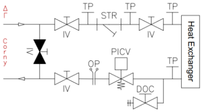
BSRIA BG 29/2021 Pre-commission Cleaning of Pipework Systems provides pipework schematic for common equipment arrangements with valve locations for testing, draining, venting and flushing systems which are featured on this page.
The following content is available on this page - Click on a link to view
Details on Air Vents for removing air from hydronic system, details on Drain Valves to drain water from a system to flush cleaning fluid and detritus material & requirements for the provision of in-line Strainers to protect system components from problems caused by foreign matter within piping systems.
Plus information on Test Points for measurement of pressure and temperature, requirements for Bypasses to protect sensitive equipment & Further Information bullet points.
Introduction
Hydronic system pipework arrangements should be configured to avoid airlocks and laid to falls to facilitate draining, with strainers provided to protect main plant and flushing bypasses located before all plant and equipment. Effectively cleaning a hydronic system is very much dependent on the adequate provision of air vents, drain points and the bypassing of equipment for system flushing.
Equipment such as chillers, low water content heat exchangers, small-bore control and regulating valves and flow rate monitoring equipment will be prone to blockage if dirt is allowed to accumulate in the system. Therefore, the sensitivity of plant items and the system complexity must be considered when selecting and locating air vents, drain points and strainers to ensure effective cleaning and flushing and efficient operation in use.
A message from a sponsor
Air Vents
The removal of air is important for obtaining repeatable flow measurements during commissioning and avoiding problems associated with corrosion or bacteria proliferation in operation. Therefore, pipework systems should incorporate facilitates to remove trapped air during system filling.
Vents should be used for system filling and automatic air vents should not be relied on for maintaining an air free system during normal operation. De-aeration units may need to be considered in large and difficult to vent systems.
Maintaining Positive Pressure
In a sealed system, the system pressure must be set at the pressurisation unit and expansion vessel to ensure there is positive pressure in all parts of the system under all operating conditions. It is critical to avoid negative system pressure which could lead to air being induced through automatic air vents or pipe fittings.
Locations
To release air during system filling, each pipework section and change of elevation should contain manual air vents at high points in both the flow and return pipes. Air vents should be installed at points where the water velocity is relatively low for maximum air venting efficiency; only an issue when the fluid is circulating in the system.
In general, air vents should be provided at high points, on flow and return pipework at the ends of each horizontal run, and at the tops of each self-draining section to prevent air blockage. All terminal units should have a venting valve at the highest location.
Air vents should be fitted to low loss headers mounted vertically to trap sludge at the bottom, while air in the system will rise to the top from where it can be removed.
Temporary air vents may be required on blanked ends to permit the pipe section to be vented.
Schematic details of manual and automatic air vents installed at the top of a riser


The above details are based on BSRIA BG 29/2021 figure 8 (detail G).
Size
Air vents and pipe connections should be line-size up to 25 mm, then minimum 25 mm. Air vents of a minimum size 25 mm should be installed at the tops of large flow risers.
Installation
Pipework arrangements should be configured to avoid airlocks and laid to falls to facilitate draining. Typically, air vents (suitable for the system temperature and pressure) are installed above the pipe service at the highest point in a vertical branch using a tee fitting. Connections to terminal units from the top of the main or at an angle of 45 degrees to the vertical, rather than the side or bottom, will help prevent the ingress of contaminants. Top connections on pipe distribution will assist air venting and reduce the requirement for air venting valves on branch distribution pipework. Eccentric reducing sockets should be used where changes of bore are made in runs of nominally horizontal pipework to facilitate air venting and drainage.
Air vents should be installed at points where the water velocity is relatively low for maximum air venting efficiency; only an issue when the fluid is circulating in the system. This can be achieved by installing air vents on an air bottle (on pipes larger than 15 mm) or in a section of pipe with an increased diameter, usually 2.5 times diameter of the pipe section.
Air vent and air release pipes installed where freezing is likely to occur must be insulated.
Air Vent Isolation
Manual air vents will comprise an isolating valve in the branch. Isolating valves should be provided before all automatic air vents -some manufactures offer AAVs with a shut-off valve option. To avoid leakage risk during system operation all isolating valves should be normally closed. Isolating valves must be located no more than three pipe diameters from the tee fitting to avoid dead legs.
Manual Air Vents
Manual air vents simply consist of an isolating valve in a branch pipe at high points in the system. For convenience, air release tail pipes should be run to low level (within 1.4 m of floor level, ideally over a drain if possible) collection points with a local isolation valve.
Air Bottles
BESA TR/20 states that air bottles should be formed by a square branch weld or tee extension pipe, terminating in a reducer or cap with 10 mm tail pipe to a 10 mm needle valve in an accessible position. Air bottles shall be not less than 2 pipe diameters long or 150 mm whichever is the greater.
Automatic Air Vents
Manual air vents should be provided in preference to automatic air vents (AAV), however in locations difficult for regular access automatic air vents may be fitted. Automatic air vents should be isolated during normal system operation to avoid the risk of leakage. Automatic air vents should not be relied on for maintaining an air free system during normal operation.
BESA’s TR/20 advise is for automatic air vents (automatic air eliminators) only to be fitted at high points difficult for regular access. Bleed pipes from these, shall be run to a clearly visible position.
Venting Domestic Water Systems
Cold water systems do not normally require venting points, however domestic hot water circulation systems are prone to air locking. Whilst air will be released at draw off points, additional provisions will normally be required at high points.
Drain Valves
Provision must be made to drain water from a system to flush cleaning fluid and detritus material. Drain valves should be installed at low points and local to all plant and equipment.
Adequately sized drain connections for flushing and cleaning purposes should be fitted. Drain valves should be of the ball type to avoid clogging.
Locations
Drain valves should be installed at low points and local to all plant and equipment. All drain valves must be in an accessible position at the lowest point so that accumulated sludge may be removed safely and effectively from the lowest point. Dirt pockets should be provided at the bottom of risers.
Drain connections should be fitted on both sides of major plant items (chillers, boilers, heat exchangers, calorifiers, expansion vessels, storage tanks, water heaters, etc.), any item with a large water volume, main primary and secondary return pipes to facilitate the flushing of each circuit, at the end of circuits, at dead-leg locations and at all terminal units (fan coil units, duct mounted coils, radiators, under floor heating manifolds, etc). Provision for the sectional drain-down of all parts of a system and separately zoned areas must be made.
Drain points should be provided on water storage tanks where the invert of the drain connection should be positioned to provide maximum drainage of the tank. The drain points should be at the base of the calorifiers and vessels.
Adequate provisions for isolating and draining sections of cold water distribution pipework will ensure that disruption caused by frost damage can be minimised.
For water sampling purposes include drains around main plant items, system extremities, areas of low water velocity (such as terminal branches), or areas that may have been temporarily isolated.

The above details are based on BSRIA BG 29/2021.
Size
BESA TR/20 states that drain cocks shall be 15 mm, 20 mm or 25 mm, whichever is closest to the main size. BSRIA BG 4/2007 recommends drain valves to be line size up to 40 mm and minimum 50 mm for all larger sizes. Draining low points on heating sub- branches shall be by 15 mm drain taps.
Installation
Pipe services should fall continuously towards drain points. All draining taps should be capable of being fitted with removable hosepipes unless installed over a drain or discharging into a permanent draining pipe.
Adequate clearance, typically 300 mm minimum, must be left above the floor to facilitate the coupling of flexible full-bore drain hoses. A flanged end should be provided for emptying and cleaning of dirt pocket surfaces.
Strainers
In-line strainers are required to protect system components from problems caused by foreign matter within piping systems.
Strainers will minimise fouling or damage from scale, rust, installation fragments, etc. Correctly located, strainers remove large solids before they can enter components such as pumps, chillers, boilers and control valves. Whilst primarily provided for the flushing process strainers also provide component protection during system operation. A suitable mesh size for this purpose is approximately 0.8 mm. Strainers should have a basket capable of withstanding the maximum pump head without distortion.
Locations
Strainers should be provided in pipework connections to central plant (chillers, boilers, heat exchangers, etc.), in front of all pumps (especially if used for system flushing) and on main branches at risers or zone connection locations to trap debris that might enter final terminal units.
Strainers should be provided upstream of pressure reducing valves, three-way mixing valves on secondary circuits and local to any sensitive equipment. Major terminal unit coils and plate heat exchangers should be protected by local strainers which provide the additional function of protecting the associated control valve and flow measurement device.
Limiting The Quantity Of Strainers
Checking and cleaning a large quantity of strainers, particularly those with a fine mesh size, will be labour intensive and costly during initial setup and routine servicing. Therefore, as per BSRIA BG 29/2021 figure 5 (detail D), strainers are only provided on main branches from risers to remove debris and should be sufficient to protect local room terminal units and control valves where flushing bypasses are installed but no additional strainers.

The above details are based on BSRIA BG 29/2021.
Installation
Strainers should be fitted as close as possible to the components they protect and should be provided with a means of local isolation. If there is a significant length of steel pipe between the pump and any plant item which cannot easily be looped out during the clean, an additional strainer should be included at the inlet point.
Strainers should be installed in horizontal pipework with the strainer basket in the direction of flow pointing down. If a strainer can only be installed in vertical pipework, the flow must be in the downward direction.
The installation should allow space clear of fixed obstructions or other services for routine withdrawal of the strainer basket and include adequate access for maintenance and replacement.
Pressure test points should be provided across strainers to facilitate monitoring of the pressure drop. On DN50 and larger strainers, the inclusion of a drain valves on the flanges and/or end caps of Y strainers to facilitate local draining of the strainer body and adjacent pipework prior to basket removal and emptying will be beneficial.
Domestic Water Systems
Strainers in domestic water systems must be regularly checked and cleaned usually annually or on a frequency defined by risk assessment or to follow manufacturer's recommendations. This will necessitate the inspection, descaling and disinfection of any strainers or filters associated with thermostatic mixing valves (TMVs).
Strainers can be a source of microbial contamination including Legionella and should be included in routine cleaning, maintenance and disinfection procedures.
A message from a sponsor
Test Points
Test points allow safe measurement of pressure and temperature providing an indication of system performance in a hydronic system.
Test Points (Pressure Test Points or Test Plugs or Binder Points -Binder is the exclusive manufacturer of the Twinlok® Test Plug) are installed on pipework to permit both pressure and temperature testing using handheld test apparatus with 'needle' type push-in probes at a single location or across components where fixed temperature and pressure gauges would otherwise be installed.
Locations
Pressure test points are required on both sides (inlet and outlet or suction and discharge) of most components so that the pressure drop can be monitored. Measurement test points are used for commission set up and are supplied as an integral part of flow measurement devices. Test points are used with Pressure Independent Control Valves (PICVs) to ensure there is sufficient pressure for the valve to operate (typically around 12 - 14 kPa); flow measurement cannot be obtained at the PICV test points. In pressure independent controlled systems, fixed orifice plates with test points are used for verification of flow measurement.
Test points should be provided across the flanges of all pumps, across the flow and return connections to all boilers, chiller and other heat exchangers, deaerators, across all strainers and non-return valves, on all ports of control valves, across double regulation valves and at heating and cooling terminal units.
Locations for Test Points


The above details are based on BSRIA BG 29/2021.
Installation
Standalone test points are normally installed in pairs or are supplied as an integral part of flow measurement devices, orifice plates, regulating valves, differential pressure valves, pressure independent control valves (PICV), etc.
All test points must be located at the side of pipework systems, not at the top or bottom where they can become air locked or trap dirt.
Typically, test points have either a red or blue coloured visual indicator plastic strap which retains the dust cap when pressure measurements are being taken. The red strap test point should be installed in the upstream or flow of a circuit and the blue in the downstream or return.

Test points should be installed on straight lengths of pipework a minimum distance equivalent to 5 diameters on the inlet and 2 diameters on the outlet of the component. For orifice plates installed alone or closed coupled to full bore isolating valves distances are 10 diameters upstream and 5 downstream (see BSRIA BG 2/2010 Table 6). On a pump outlet, the straight lengths of pipework between the pump and valve or test point inlet should be a minimum of 10 diameters.
The installation should allow space clear of fixed obstructions or other services and at least 200 mm clearance from pressure test points must be allowed to enable manometer tubes to be connected without kinking (see BSRIA BG 2/2010 4.6 Accessibility).
Extension spindles shall be used to extend test points above the line of thermal insulation for fully accessibility. The insulation must be dressed and sealed watertight around test points to maintain the vapour seal and not compromise the outer finish of the insulation.
Bypasses & Flushing Points
Provision must be made to adequately clean and flush hydronic systems.
New or refurbished hydronic systems need a pre-commission clean to remove installation contaminants which are likely to lead to blockages, corrosion, scale and microbiological hazards that will reduce the lifespan of a system.
Flushing drain points and flushing bypasses should be provided in hydronic systems to flush clear installation debris and allow chemical cleaning without circulating dirty water or chemicals through central plant, terminal units, or other sensitive equipment. Consideration should be given to the 'Flushing Velocity' and should be based on the largest pipe size in the system section to be flushed.
A flushing bypass is a pipework arrangement that temporarily links the flow and return pipes within a hydronic system short-circuiting equipment, or plant. Flushing bypass assemblies can also be used when servicing or replacing equipment by forward and back flushing to clear contaminants.
Flushing Points
Line size flushing drain valves should be provided on flow and return connections to central plant and terminal units to enable these items to be flushed through. Flushing fill points should be fitted in both the primary and secondary side return connections, at the base of riser dirt pockets and at end-of-run locations.
Flushing fill points fitted either prior to each secondary circuit pump or at a low loss header will facilitate flushing the secondary circuit. Low loss headers should be mounted vertically to trap sludge at the bottom with a flushing drain point.
Isolation & Bypasses
Systems should be designed to enable the isolation and bypassing all equipment likely to be sensitive to the flushing and cleaning process. Sensitive equipment includes boilers, chillers, plate heat exchangers, heat interface units, heating and cooling coils, chilled beams, terminal units, control valves, and low flow regulating valves.
Bypasses should be located as close to the equipment connections as possible.
A flushing bypass provided at a calorifier, or vessel will reduce the volume of water flushed to drain during the cleaning process, particularly on large vessels.
It is not recommended to flush through PICVs. Where a PICV is installed for end-of-run temperature-controlled bypass, the PICV should be either isolatable and demountable or have a bypass immediately prior to the PICV to facilitate flushing. On terminal units, the drain should be located on the return connection before flow measurement devices and PICVs to ensure a low resistance flow path through the unit to drain.
Bypasses Installation Details


The above details are based on BSRIA BG 29/2021.
Installation
Bypass pipe arrangements shall comprise full-bore isolating valves (fully open during flushing) to provide a low resistance flow path. Fixed or temporary full-bore bypasses should be provided as close as possible to the plant items they are protecting. Bypasses should incorporate downstream flow and return isolation valves to prevent short circuiting during subsequent system operation to protect equipment from the flushing process.
H pattern flushing bypass assemblies are offered with pre-assembled valve kits. H pattern bodies with 2 valves offer a compact design capable of simultaneously opening the bypass whilst isolating the downstream pathway.
Where the design of the bypass might create dead legs that exceed three pipe diameters in length, two isolating valves should be installed (one at each end), within three pipe diameters of the main flow and return pipes.
At terminal units an end-of-line bypass should be fitted which may take the form of a temperature-controlled bypass such as a pressure independent control valve (PICV) controlled to open when the sensed temperature in the pipe drops below its set point value. The PICV should be isolatable and demountable to facilitate flushing.
End of Run Bypasses
End of line (or zone) bypasses are used to maintain a minimum flow and temperature in a circuit when no flow passes through a terminal devices and associated control valves. Locating by-passes at system extremities will ensure the flow of water treatment chemicals will be maintained and the pipes will remain "live" ready for a quick response to heating or cooling demand. The minimum flow is usually dictated by the pump turndown minimum flow rate.
In a heating system the bypass will increase the return water temperature and reduce overall system efficiency, therefore it is essential that bypass flow rates are kept as small as possible. A pump bypass can be used to maintain the pump minimum flow and an end of run bypass can be incorporated that is normally closed and only opens intermittently, in response to temperature falling below a set point value. For further information refer to BSRIA 29/2021 Figures 4 (Detail C) and 5 (Detail D) and CIBSE Design Guide Heat Networks (2021).

PICV
Pressure independent control valves combine the function of a double regulating valve, a differential pressure control valve and a two-port control valve within a single valve body.
Dead Legs
A dead leg is a section of pipe which, under normal operating conditions, will not experience any flow.
Venting Velocity
The water velocity passing air vent connections should ideally be in the range 0.2 to 0.4 m/s.
Suggested Reading
BSRIA's BG 29/2021 Pre-Commission Cleaning of Pipework Systems Amended 6th edition (here )
A message from a sponsor
Air Vents, Drain Valves & Strainers > id: hvac-16 (v.7.0)