Analogue & Digital Controls
AI-AO vs DI-DO
Homemicro.co.uk explains the difference

HVAC systems are controlled by Building Management Systems (BMS) or Building Automation Systems (BAS) using Direct Digital Control (DDC) devices which can receive and process inputs and send command outputs.
The inputs are either Analogue Input (AI) or Digital Input (DI) reactions and the outputs are analogue Output (AO) or Digital Output (DO) actions.
The following content is available on this page - Click on a link to view
Types of Input: AI Analogue Input and DI Digital Input, types of Output: AO Analogue Output and DO Digital Output.
Information on switch states Normally Open or Closed, plus Sensors & Switches and VSD Variable Speed Drives.
Analogue & Digital
Analogue (or analog):
Having continuously variable (modulating) characteristics representing physical measurements.
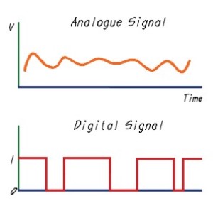
An analogue signal is a continuous signal that contains time-varying quantities representing physical measurement. An analogue input is a variable signal that either measures a voltage (0-10V) or current (0-20mA) from an input device and an analogue output will supply a variable voltage or current signal.
Analogue I/O is used for devices which are continuously changing or variable.
Digital:
Signals that have discrete (individually separate and distinct) values at each sampling point.
Digital refers to the state of a single-bit, or binary (0 or 1) signal. This binary signal has two states: ON (binary 1) and OFF (binary 0).
Digital I/O is used for ON/OFF (Start/Stop) control or devices that trigger an action such as limit or fault switches.
A message from a sponsor
AI - Analogue Input
Analogue input (AI) refers to a continuously changing voltage or current signal to indicate a changing state. An example is a sensor that monitors physical data change over time, such as temperature, flow, or pressure.
Example Applications:
- Temperature
- Humidity
- Pressure
- Airflow
Use:
- Temperature sensor. A space temperature sensor measures and reports the changing room temperature. This information will be used to vary the output of heating and cooling plant supplying the room, but could also be logged to provide an historic record of the space conditions. Maintaining records is useful for fault finding.
- Pressure sensor. A duct pressure sensor will measure and record air pressure.
AO - Analogue Output
An Analogue output (AO) is a variable signal to a process control such as a motor speed controller or a valve actuator. A variable AO signal to a motor will control the speed where 0V = OFF and 1-10vdc = 10%-100%. Similarly, a control valve can have a variable position between open and closed with a variable analogue output.
Example Applications:
- Fan speed
- Variable Air Volume (VAV)
- Damper actuators
- Boiler modulation
Use:
- Fan speed. A variable speed drive (VSD) fan motor speed may be modulated to match the actual humidity or temperature in a space to either increase or decrease the air flow rate delivered to the space. The system will continuously respond to changing conditions in a space and adjust the fan motor speed appropriate for the actual demand, providing control of the space environment whilst efficiently regulating energy consumption. Refer to notes on variable speed drive
- Variable Air Volume (VAV). VAV systems supply air at a constant temperature to heat and cool a space. As each space will have varying heat demand, each VAV box must modulate the airflow to maintain stable temperature conditions. Each VAV box has a motor/actuator that modulates a damper position allowing variable amounts of airflow into the space.
- Boiler modulation. A BMS can directly control a boiler (or multiple boilers) with a 0-10 volt analogue output by regulating either the temperature set point (usually limited up to maximum 85°C), or the burner load setting up to the maximum 100% output. Where boilers are supplied with the manufacturers proprietary controls, the signal from the BMS will be DO.
DI - Digital Input
Digital inputs (DI) to a controller include plant status switches and inputs from other control, monitoring and alarm systems. DI will indicate the status of a device as either ON or OFF and can therefore indicate failure or fault status. With a 24Vdc control module 0V indicates the OFF state and 24V the ON state.
A digital input registers the state of an input from such devices as a tank level switch or a door-closed switch.

Example Applications:
- Status (on/off, airflow, run, open/close)
- High/low limit switch (alarm or normal)
- Alarm
- Trip
- Air differential pressure switch.
Use:
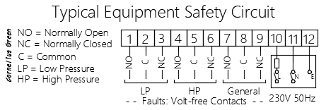
- Pressurisation unit. A commercial unvented heating system will have a pressurisation unit with high and low pressure limit switches which will indicate a fault condition if either state is detected – refer to the image above.
- Water tank level switch. A limit switch is an electromechanical device that detects the presence or absence of an object when physical force is applied by an object. A high level switch is used to indicate a tank is overfilling perhaps due to a water fill valve failure, whilst a low level switch would indicate a loss of water supply to the tank.
- Plant pressure limit. A high pressure switch on a boiler will prevent the burner from firing should the internal boiler pressure exceed 6 bar (may vary by boiler type/manufacturer) and release for operation once the pressure drops to 5.8 bar. A low pressure switch on a boiler will modulate the burner to 20% modulation should the internal pressure drop below 1 bar, and prevented firing should the internal pressure drop below 0.8 bar. Once the internal pressure recovers to 1 bar the burner will operate at 20% modulation until the pressure reaches 1.2 bar when full burner modulation resumes. This may vary by manufacturer or boiler type.
- Air differential pressure switch.
DO - Digital Output
Digital outputs (DO) from a BMS outstation are used to switch equipment on or off (enable or disable a device),usually via relays or contactors.
Digital output signal contains the state of an output to such devices as a motor starter or panel signal light. A digital output will change or maintain a device status by performing momentary or maintained switching to start/stop pumps, fans, etc.
DO can be used to operate two-position solenoid valves (open/closed), relays, indicating lamps, etc.
Example Applications:
- Command (on/off, open/close)
- Boiler enable
- Extract fan enable
Use:
- Boiler enable. Boilers provided with the manufacturers proprietary controls which provide burner firing modulation and cascade control in multi-module installations will receive an activation signal only from the BMS.
- Extract fan enable. A toilet extract fan could be activated by a motion sensor which provides enable/disable signalling.
Normally Open or Closed
Normally Open (NO)
A circuit that is open with no current flow when the contacts are not actuated. That is, the switch is 'off' and there is no electric circuit or signal.
Normally Closed (NC)
A circuit where a contact is closed in the normal state allowing electrical current flow.
Sensors & Switches
Sensors
A sensor translates a physical property (variable – pressure, temperature, humidity etc.) to an electrical signal. In broad terms, sensors provide variable measurement and are therefore associated with analogue points. Intelligent sensors which convert the measured value or status of the measured variable into a digitally encoded signal are available.
BMS controls analogue devices include resistance thermometers, potentiometers and voltage or current-operated devices, normally functioning in the range of 0-10V or 4-20mA.
Analogue sensors will measure the variable and convert the value into an electrical signal which is input to other devices for measurement and control purposes. Usually functioning within in a range or scale where 0V represents the lowest measured value and 10V the highest.
Switches
A switch will trigger at a specific set point (fixed – pressure, temperature, humidity, etc.). Switches infers digital control with [on/off] status indication.
Variable Speed Drives
Variable speed drives (VSD) are used on motors for pumping fluids or moving air to regulate flow and conserve energy. A VSD is usually controlled by an analogue input from the BMS to modulate the motor speed, however a digital input could be used to start and stop the motor automatically. In the latter case the motor speed would be fixed and set at commissioning.
An analogue output could be used to provide speed, current and torque signals to the BMS.
A digital output would normally be used to indicate a fault with the VSD.
ADC
Analogue-to-Digital Converters (ADCs) allow micro-processor controlled circuits (which use digital logic values 0 and 1) to communicate with a variable 0-10 volt analogue signal. An ADC takes an analogue voltage signal and converts it into an equivalent digital signal.
BMS, BAS & BACS
Building Management Systems (BMS) or Building Automation Systems (BAS) or Building Automation and Control System (BACS) are automatic centralized controls for buildings
What's Included
A BMS can control HVAC (heating, ventilation and air conditioning), lighting, windows & shading, access control, security systems, and other interrelated systems
A message from a sponsor
AI-AO vs DI-DO id: hvac-05 (v.7.0)