Buffer Vessels (Thermal Storage)
This article provides a quick overview of buffer vessel sizing.
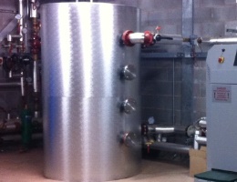
A buffer vessel is a cylinder or container that holds water, increasing the overall water volume content of a heating or cooling distribution system. The additional water volume absorbs heat (thermal energy) produced by the heating appliance (or cooling from a chiller) in low load conditions, which the building or system does not yet require principally to prevent plant short cycling.
Why Use A Buffer Vessel?
A buffer vessel or thermal store, captures thermal energy (heating or cooling) to provide a buffer between load variations in order that the plant appliance efficiency can be optimised, thus alleviating slow response issues. A buffer vessel is designed to provide additional water volume or inertia to the system. A buffer effectively prevents cycling of the thermal source when the system demand is less than the plant minimum output. Reducing plant cycling is important to prolong the plant life and minimise harmful emissions of CO and NOx.
Buffer Vessel or Thermal Store:
There are two vessel variations either a Buffer Vessel used to capture residual heat (thermal energy) on shut-down to improve system efficiency or a Thermal Store which enables a small thermal source to serve a system with a higher capacity.
Buffer Vessel:
- Dissipates thermal energy from the plant on shutdown
- Protects plant from overheating
- Improves overall efficiency
- Stored thermal energy can be used by plant on start-up
Thermal Store:
- Plant can be sized at less than 100% of the system heat demand
- Allows plant to operate continuously for long periods
- Will serve function of a buffer vessel (takes thermal energy on shut-down and feeds the plant on start-up as required)
Where the plant is the thermal energy source providing heating (boiler, CHP, ASHP, etc.) or cooling (chiller system).
A message from a sponsor
Buffer Vessel Sizing
For most simple installations, one of the four methods below can be used to size a vessel. For more sophisticated heat networks which have large system volumes a vessel is likely to play a crucial operational role and will require more careful selection. Refer to heat network sizing
Vessel size will depend upon the application, heat output, fuel quality, minimum acceptable on-time cycle of compressors (ASHP & GSHP), the operating temperature differential of the [vessel], controls, hours of operation, etc.
Basic Rule
The following general definition will determine a vessel size: Vessel capacity = (required system volume) - (actual system volume)
Where the required system volume is that necessary to accommodate the thermal output of the plant and the actual system volume is the water volume in all pipework and heat emitters.
Here are four rule of thumbs which can be used to determined the vessel size depending on various factors such as the heat source and fuel quality:
Litres per kW
A rough rule of thumb would be to size a vessel volume according to the heating or cooling plant size applying a nominal volume per kW. This follows the basic rule to establish a required system volume.

Where the central plant has redundant capacity (run and standby), the plant size value should normally be equivalent to 100% of the connected capacity, not the total plant load.
Minimum Run Time
Where a [buffer] vessel is provided to reduce cycling of equipment, the size should be determined by the number of starts per hour.

Selecting a minimum 6 minute runtime (t) would be a good starting point, although 10 or 20 minutes may be more desirable.
The same calculation can be used to account for minimum run-on time. Heat sources such as biomass boilers require a minimum run-on time, so that residual heat is removed from the boiler as it cools down.
CIBSE Design Guide Heat Networks (2021), paragraph 3.4.1 details calculations for buffer vessel volume sizing that include allowance for heat source minimum run time (Vr) and minimum run-on time (Vro).
Smallest Zone
Selecting a vessel to meet the demand of the smallest controlled zone ensures there is readily available capacity to at least serve that zone and prevent cycling of a [large] heat source.

Selecting the zone with the highest dependency, a north facing zone or area with a high heat loss ratio may be an alternative consideration.
Flow Rate Percentage
A simpler variation on the smallest zone method is to calculate the vessel size based upon a percentage of the heat source flow rate as only a small capacity is accounted for, and no zone heat load information is required.

Typically used for an air source heat pump (ASHP) installation by determining the buffer vessel size to match 10% of the water flow rate of the heat pump/hour for a single compressor unit and 8% for a twin compressor (as the second compressor provides load diversity).
Allow a margin—
Include a margin on all results. The vessel volume calculated is the anticipated usable volume and an operational margin (or utilisation factor) may be required to allow for uncertainties in the calculation method.
Download the Guide—
The homemicro.co.uk detailed guide on thermal store sizing is available here
Heat Network Sizing
The sizing of a buffer vessel or thermal store in a heat network, such as a district heating system that distributes centrally generated heat to dwellings, buildings or properties to be used for space and hot water heating, requires more considered planning.
New heat networks are likely to comprise multiple heat sources comprising fossil fuel plant, low carbon and renewable, with each source operating at varying inlet and outlet flow temperatures. Heat network systems should be optimised for the lowest carbon heat sources to meet heat demands in preference to other, less carbon efficient heat sources. A vessel will help achieve this. Vessels also provide hydraulic separation between the energy centre primary circuit and the network primary distribution circuit.
Sizing a vessel for heat networks is cover in the CIBSE Design Guide: Heat Networks (2021) – see the guide here
The CIBSE Heat Networks guide follows 5 steps to establish the volume from Vr, Vro, Vts and Vp. Where the vessel volume (V) is the buffer volume for minimum run time (Vr) plus the maximum of either: minimum run-on time (Vro); store for heat generated earlier (Vts); or volume for high short-term loads (Vp). This approach sizes the vessel for both buffer and thermal storage capacity to ensure the heat sources and thermal store operate to always deliver more heat than the network requires.
Calculating Vts can be complex as it involves modelling of the daily heat usage pattern of the network at different times of the year. Daily heating and hot water loads need to be identified along with heat inputs to the network from each heat source and the thermal store, and the heat source input to the thermal store.
Sizing For Different Heat Sources
Some rule of thumb examples for different heat generating plant.
ASHP • BS EN 15450:2007 suggests sizing the buffer storage volume at 12 to 35 L per kW maximum heat pump capacity.
Biomass • Size between 10 and 20 litres/kWth plant capacity (CTG012); a lower value may be used where loads do not fall to zero, for pellet fuelled boilers which are more responsive and for boilers with a low turndown capability. Where low grade wood with a high moisture content is used, the storage volume may need to be sized at up to 40 litres/kWth.
Chilled Water • For general cooling around 2.5 to 8 litres per kW or between 8 to 14 litres per kW when temperature accuracy is critical.
GSHP • For intermittent use heating load (kW) x 25 (L) and for continuous use heating load (kW) x 80 (L)
Reasons for a Vessel
Benefits for using a buffer vessel or thermal store include the following:
- System stability • a vessel provides sufficient water volume and adds inertia to the system, reducing the cycling frequency of heat sources at low load
- Management of defrost • stored heat can be delivered during a defrost cycle to provide continuous supply
- Peak-lopping • large storage volumes can be used to meet demand at peak times, for example during a DHW peak
- Heat sharing • storing waste heat from earlier in the day
- Resilience • providing a buffer should the heat source temporarily fail
- Energy costs • delivering flexibility, allowing users to take advantage of time-of-use tariffs
Tank, Vessel or Store?
| Term | Definition |
|---|---|
| Accumulator Tank | A buffer vessel or thermal store |
| Buffer vessel | A vessel that captures residual heat on boiler shut-down preventing frequent boiler start-ups to improve system efficiency. It will also reduce the energy required from an auxiliary boiler. Usually has a simple on/off control strategy. |
| Thermal Store | A vessel that is charged by the biomass boiler when the boiler output exceeds the load demand enabling a small biomass boiler to meet demand. A progressive control strategy using several temperature sensors will control the boiler output. |
Suggested Reading
CIBSE Design Guide: Heat networks (2021)
BSRIA BG 7/2009 Heat Pumps a guidance document for designers
A message from a sponsor
Buffer Vessel id: hvac-04 (v.7.0)